


")

")


Insulated Render Systems Installation Guide

Insulated Render Systems Installation Guide
In this blog we will be talking about installing an Insulated Render System also called Thermal Render System, Exterior Insulation Finishing Systems (EIFS), EWI (Exterior Wall Insulation Systems) or External Thermal Insulation Composite Systems (ETICS).
We will be concentrating on thin coat silicone based texture renders. The installation process is generally the same for most systems but please contact and follow the chosen manufacturer’s recommendations and guidance. Different systems and manufacturer’s requirements vary so the system chosen will need to be verified.
Main steps of the installation of Insulated Render System (explained in detail later):
- Inspect and prepare walls
- Prime walls before insulation
- Place starter tracks and flashings
- Fix insulation
- Install corner, stop, drip, window and door beads
- Apply base coat render with reinforcing mesh
- Prime basecoat before final coat
- Apply finishing render
Generally, a system, contains the following construction build-up:
- the substrate structure (ex: brick, concrete or masonry walls)
- adhesive, if applicable to the system, with a mesh layer (depending on the system)
- Fixing through the insulation or through the mesh
- Insulation boards
- Base coat
- Embedded mesh
- Base coat
- Final finish
With each EWI system consisting of the following components:
- Insulation
- Mechanical Anchors / Fixings
- Adhesive (Renders)
- Reinforcement Base coats and Reinforcement Mesh / Lathe
- Polymer Modified Cement Base coat renders or Organic non-cementitious basecoats
- Polypropylene / Glass fibre mesh, metal lath
- Primers
- Surface finishes
- Beads, trims and flashings
Finishes
There are many finish types including:
- Silicone render
- Acrylic render
Other render types include:
- Mineral
- Resin Based Mosaic
- Brick and wood effect renders
- Dry dash
- Wet dash
Each system design will have its own range of material types and effects. Different finish options provide a different visual aesthetic, however each will have specific criteria on application, location and height. Some of the common types are indicated below.
Finishes that we will be talking about in this article are thin coat stone textured and consist of acrylic, silicone resin, silicate or cement binders. They are shaded with aggregates in either white or a with coloured binder. Application can be applied with a stainless trowel or sprayed. Large areas can be done at a time although all textured finishes must be hand finished using a flexible plastic float. As the binders can vary between organic (synthetic) or mineralic, the properties of the finish material also vary greatly with changing formulation. The most common size of texture specified tends to be 1.5mm as this is the smallest surface grain that can start to disguise the hand applied nature of the base coats in poor lighting.
Insulation Materials
There are various insulation materials available, They vary in terms of thermal performance, composition and installation requirements:
- EPS (Expanded Polystyrene) - available in White (Standard) and grey (Enhanced)
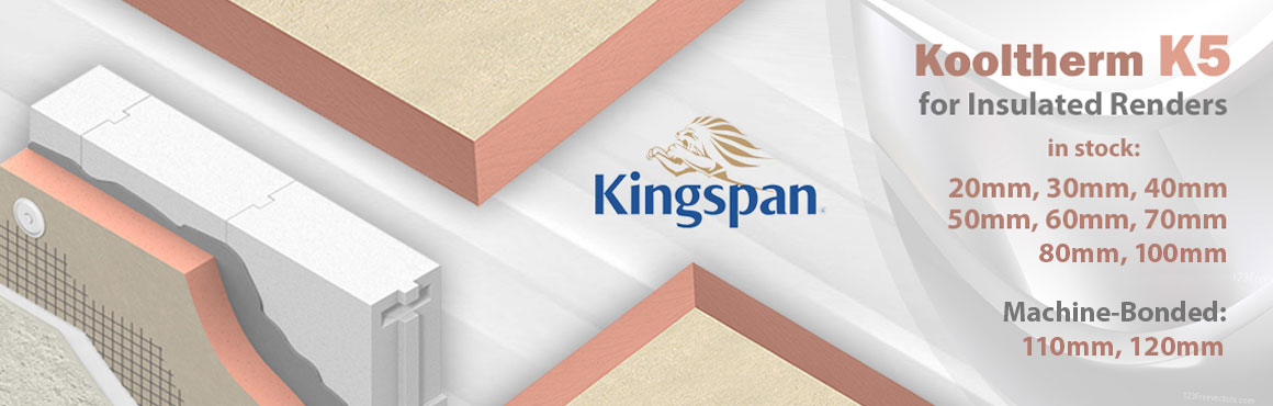
- Phenolic Foam (ex. Kingspan Kooltherm)
- PIR (Polyisocyanurate)
- XPS (Extruded Polystyrene)
- Mineral (Stone) wool / glass wool
- Cork
- Wood fibre insulation
EPS (Expanded Polystyrene)- White (Standard) and Grey (Enhanced)
Expanded Polystyrene (EPS) is a lightweight, rigid, plastic foam insulation material. It is a cost-effective, easy-to-use insulation for EWI applications. As the structure of EPS consists of 98% air, its initial thermal properties are maintained throughout its working life. It is non-toxic, moisture resistant and rot proof.
EPS is supplied in standard white material and an enhanced thermal performance (low lambda) material which is in most cases grey in colour. A wide range of thicknesses are available to achieve the thermal values required.
EPS is classed as combustible, however combustibility is limited due to retardants present. It has a high K-value when compared with other insulations.
Phenolic Foam
Phenolic foam is a closed cell insulation with very good lambda values, which makes it the most thermally efficient insulation on the market. (One example is Kingspan Kooltherm boards.) The cells are formed by the evaporation of a high-performance blowing agent, which has negligible global-warming potential and zero ozone depletion potential, leading to a better thermal value than other insulations. It is easy to use, and has good fire resistance properties, although it is not classed as non-combustible; however combustibility is limited due to retardants present.
PIR (Polyisocyanurate)
PIR foam is a closed cell insulation, with good lambda values. The cells are formed by the evaporation of a high-performance blowing agent, which has negligible global-warming potential and zero ozone depletion potential, leading to a better thermal value than other insulations. It is easy to use, and has good fire resistance properties, although it is not classed as non-combustible; however combustibility is limited due to retardants present.
Mineral (Stone) wool / glass wool
Mineral (Stone) wool or glass fibre insulation is manufactured from molten rock or silica sand heated and blown to form thin fibres with binders and oils to produce an insulation with good thermal properties, but excellent fire resistant properties. It is classed as non-combustible. It is easy to use, and is the only insulation to be classed as “non-combustible”.
Cork
Cork insulation is a relatively new insulation to the EWI market. It is 100% natural with a cellular structure which makes it a natural insulator. Cork has natural fire inhibitors making it fire-retardant but is classed as combustible. Cork also has a good thermal value.It has an A+ rating in the Green Guide to Specification.
Wood Fibre
Wood fibre insulation is manufactured from wood chippings and natural binders. It is both vapour permeable and hygroscopic. It is easy to use, and gives good lambda values. It has good thermal mass properties, meaning heat is stored and then released as the temperature drops.
Installation guidance:
General Notes:
- It is recommended to use an approved installer to carry out the works, trained, assessed and approved by the relative manufacturer’s system.
- Speak to the Local Planning Department to evaluate if planning permission is required. This is particularly important if the property is Listed or located in a Conservation Area or Area of Outstanding Natural Beauty.
- Contact the Local Building Control Authority to inform them about the work being done in order to get the appropriate Certificates of the construction work. Alternatively, an installer who is part of a SWI Person Scheme (CPS) might be able to self-certify that their work complies with Building Regulations and who will be able to submit this to the Building Control department on your behalf.
- Ensure that the works provide a continuous thermal envelope as gaps can create cold bridging, especially at junctions and poorly built and/or designed areas or commissions can create zones of potential moisture ingress.
Prior to work commencing:
- Full site survey prior to commencement of work. Include any repairs to the original wall needed and identify what pipes, ducts and equipment might need to be temporary removed or altered/ extended.
- Check if the wall is straight and plumb, as the substrate condition has an effect on the final EWI wall finish. Preparation of the existing wall substrate is crucial before the commencement of the works. Remember the finished render coat is applied by hand, usually with a plastic trowel to achieve a level, plumb wall of the appropriate wall texture.
- Verify what type of insulation will be needed and the thickness to obtain the appropriate U-value for the overall wall construction.
Step 1) Inspect and prepare walls
Site Survey Checklist prior to starting works on existing buildings:
- Check for rising damp and identify the causes
- Check for existing movement joints and ensure that these positions and new movement joints are installed in the new works
- Check for efflorescence (lime bloom) or if similar problems have been treated and remedied, such that the existing masonry is fully dry of excess moisture
- Test the walls for any defects
- Test the existing substrate for pull-out loads so that fixing types and quantities can be chosen
- Carry out a line and level survey to determine if a dubbing out or levelling coat is required
- Remove moss, lichen, mould and treat with an anti-fungicidal wash, if required
- Identify any unusual detailing issues
- Determine if any architectural features need preserving or replicating, in order to be repositioned and placed within or on the new EWI system
- Evaluate access to the property, heights of the building and security of tenants
- Chose the type of EWI system to be used including the selected finishes, colours and textures
- Ensure that the eaves and roof areas have adequate insulation to avoid cold bridging at these junctions
- Evaluate the need for repositioning of, or temporary removal and/or extension of services such as overhead services such as electrical and communication live wires, equipment, gas or oil pipe work and flue terminations, electricity or gas meters, lights, satellite dishes, rainwater gulleys, downpipes, hoppers, etc.
Identify the following before work starts (on existing or new builds):
- Position of starter tracks and render beads
- Position and amount of reinforcement scrim, corner mesh and scrim patches for corners / corners of openings
- Detailing around doors, windows, eaves, projecting balconies, coping details and special details such as abutments, extensions (robust standard solution / typical design details are available from the system certificate holder / system designer)
- Damp proof course level
- Location and type of weather seals to be used
- Areas where silicone sealants are to be used
- Position of fire barriers (if required)
- Location of movement joints
- Location and positioning of beads and trims
- Flashing details
- Window and door cill details
- Architectural features i.e. quoins, external cornicing, stringers, keystones, window headers, window cills, window architraves, corbels, arches, flat bands, raised or recessed bands, ashlar cuts and columns, etc.
- Coping details, special details such as abutments and extensions
- Adjacent features such as fences, walls, gates, clothes lines, etc.
Step 2) Primer before insulation
Preparation of Work:
Fully clean the wall surfaces of any dirt, algae, mould, etc. Clean with a power wash, and mild detergent, if necessary. Allow the wall to fully dry. Apply a primer (dependent on the chosen system), to help with the adhesion of adhesive renders.
Existing Rendered Walls:
If the wall has existing render, the render might need to be removed if in a poor state. Removal might be required for the whole wall or just weak areas. These areas should be repaired with a sand/cement mixture or a propriety render repair system. Check the exiting render for areas where damp, moisture ingress or wall breathability may be compromised.
Tests for Mechanical Fixings and Adhesive Fixings Systems Ahead of Construction:
Prior to installation check the existing wall substrate for adequacy of accepting mechanical fixings and anchors. If using an adhesive only fixing system, testing the maximum tensile strength of the render and associated materials on top of the substrate is advisable.
Plan Out the Programming of Works:
This should be done in regard to site requirements, resources, system specifications and weather conditions.
Site Protection as Work Progresses:
As work progresses, during pauses of work (i.e. overnight or other long term breaks), ensure that board edges and joints are fully protected from weather conditions, such as rain and strong sunlight. This protection might involve the covering of all areas in the construction that are not yet fully weatherproof. It is important to control drying rates of the materials / components and to prevent excess moisture from being trapped in the wall system.
Monitor the weather for 48 hours before commencing the base coat of wet renders as this needs to be installed in rain free environments.
The base coats of cementitious based renders should be applied in two coats with an incorporated scrim reinforcement layer between the two coats, plus an additional finished coat. Be mindful of thickness and cure times between layers according to the manufacturer’s recommendations. The finished coats should be protected from direct winds and direct sunlight, to avoid possible cracking due to excess quick curing.
Step 3) Place starter tracks and flashings
Generally, all EWI systems incorporate a selection of beads, trims and flashings. Each will depend on the design of the individual project. Beads and trims form the junctions and closures to the system, so the correct following of the manufacturer’s requirements are crucial. Finishes can be in stainless steel or galvanised steel, aluminium, UPVC and most finishes can be powder coated to the colour of your choice.
Design for key locations such as starter tracks that are placed directly above the damp proof course (DPC) layer. Starter tracks are essential for laying out the insulation boards. If you would like the insulated rendered wall to continue below DPC level then XPS insulation should be used with a waterproof base coat such as Aquabase. For additional impermeability, finish with a mosaic render.
In regard to materials, uPVC is a simpler installation method as it comes prepared with an attached mesh. Aluminium profiles require extra clip-on profiles. These can help with creating a drip nose to the bottom of walls and be more aesthetically pleasing, providing a clean edge to the base of the rendered, insulated wall. Aluminium are stronger, can take more weight than uPVC and resist stronger wind loads. In coastal locations, it is recommended to use stainless steel starter tracks and any exposed elements to be in uPVC or stainless steel due to salts in the air. Check with the manufacturer’s guidance when installing in these areas.
- Use a spirit level throughout installation of the starter tracks
- The appropriate fixings to the starter tracks should be placed at a maximum of 30mm c/c generally (check with manufacturers guidance)
- Use connector clips between starter track sections
- Cut the tracks at the wall corners to create a 45 degree angle joint
Allow for movement joints and expansion beads in large areas. Window reveals might require stop beads. Allow for cills and flashings to be installed with a minimum overhang to protect the finish face from excessive rain water. Best practice suggests a minimum of 40mm overhang to window cills. (Refer to BS13914:1:2005).
Some designs might require bespoke trim designs.
There are further bespoke systems available, such as insulated fascia trims, fence post brackets, satellite dish box brackets, hanging basket brackets, washing line brackets, etc.
Step 4) Fix insulation
Insulation Layer:
The installation of insulation boards should be done in dry weather, with protection from adverse weather, sunlight. Protect the boards from any potential accidental damage.
The boards should be laid in a staggered pattern with a staggered tooth edge pattern on the building wall corners.
It is advisable to cut the boards in a “L” shape at the corners of wall openings; without horizontal or vertical joints directly at the corners of wall openings. Avoid small pieces of insulation, with the smallest pieces used should be a minimum of 200mm.
Fill any gaps with adhesive foam or thin strips of mineral wool insulation.
Ensure that the boards are installed in a level plane to receive the base coat and decorative finishes. Boards can be levelled out with adhesive renders or dubbing out renders.
It is recommended to apply adhesive renders to the rear of the board; and should be applied in either a dot and dab method. Adhesives should be applied to all of the adjoining board edges or apply adhesive to the full board surface using a serrated trowel. All as per manufacturer’s recommendations.
Install mechanical fixings as per the specifications using the correct quantity and installed at a true 90 degrees to the wall face with the washer head sitting flush with the board face. If any fixings are faulty, they may require removal and additional fixings may be required.
Step 5) Render Beads - Corner, Stop, Drip, Window and Door Beads
Trims items
All beads, trims, corner edgings should be installed as per the manufacturer’s recommendations and as per the system design guidance. They should be fit for purpose and in the appropriate materials as previously mentioned above.
Pay attention to trims in sensitive design detail locations such as at eaves, verges and soffits. Ensure that these details are built with proper watertight seals. Bespoke trims might need to be made for the project’s specific requirements.
Sealants
Mastic sealants should be kept to a minimum as they have short life cycles and therefore require maintenance and replacement after periods of time. They should be checked before use to ensure that they are of the correct type and grade.
A type of sealant, which is recommended, is a “low modulus neutral cure external grade” type as it has superior flexibility than standard high modulus silicones.
The silicone sealant can be installed within the rendered finish or on the exposed surface. Best practice is to install the silicone into a 5-6mm gap or alternate approved elastomeric sealant with a finished top layer. The latter is the preferred method for thicker coat finishes such as dash aggregate, brick effect render, acrylic or clay brick slips.
PPC trims will last much longer than mastics, potentially for the life span of the system. So it is best to use trims over sealants.
Step 6) Base Coat with Reinforcing Mesh
Mesh
For thin coat renders, the mesh gets applied to the first base coat. For thick coat render system, the mesh is usually a metal lathe type, fixed to the insulation prior to the first base coat.
Polypropylene or glass fibre meshes should be installed into the wet base coat. They are pressed into it using the back of a steel trowel, sitting in the top third. Meshes should be continuous and should have a minimum 100mm lap with the adjacent mesh. All meshes that are integral to beads and trims should allow for 100mm lapping to ensure strength and continuity of the base coat.
A second base coat is thus applied leaving no visual signs of the mesh.
The base coat should be left to cure before applying the final finish, i.e. suitably scarified in the case of thick coat finishes or sponged for fine textures.
Step 7) Prime basecoat before final coat
It is recommended to use the special primers (Ceresit CT16) on top of the basecoat to enhance adhesion and coverage of subsequent renders and coatings. It also prevents decolouring of the finishing renders.
Step 8) Final Finish Coat
Generally, finishes should be applied in good weather and in ambient temperatures between 5-30 degrees Celsius. Check if your system finish has a Winter additive to be applied in colder temperatures. Finishes should be stored in an area of constant temperature and kept above 5 degrees Celsius. Acrylic and silicone renders have water in them which can freeze, thereby damaging the material. Note that powdered finishes have water added so the same applies.
Brick effect renders can result in efflorescence or lime bloom if they are installed in low temperatures or in damp, foggy weather or if there is excessive moisture in the air. This will result in a white powder appearing on the surface of the finish from the movement of the free limes in the cement. Although this does not effect the performance of the brick render.
Textured finishes should be applied with a steel trowel and rubbed with a plastic or nylon trowel to ‘reveal’ the aggregate. It is advised to always follow a wet edge and to finish at a stop bead or movement joint.
When texturing around scaffold points it is advisable to have two installers applying material above and below the scaffold point and rub up the wall at the same time and in the same direction to avoid scaffold marks. Alternatively a stop bead should be provided at scaffold level so that the finish can be applied in two separate applications.
It is best practice to split a building elevation into workable areas through the use of movement joints and stop beads, to assure a clean look finish.